Using Emulator Control Keys, Menu, and Panel
PUBLISHED
![]()
![]()
![]()
Dependencies
- Tizen Studio 1.0 and Higher
Content
Before deploying your application, it is important that you test it in an environment similar to a real device.
You can run the application in the emulator, and test a variety of user scenarios, such as network access, audio input and output, and text messages. With a mouse and keyboard, you can control the application in the emulator exactly like on an actual device.
While the application is running, you can use the Emulator Control Panel to simulate events for a variety of system options that the actual device provides. For example, by manipulating the virtual battery, you can simulate the application in different charge environments.
The emulator controls consist of internal and external parts:
- The HOME, Volume control and Back buttons, for example, are external parts controlling the device from the outside.
In the emulator, the external parts are called the emulator control keys and menu.
- Battery level and screen brightness, for example, are internal parts controlling the device from the inside. In the emulator, the internal parts are called the Emulator Control Panel.
Using the Control Keys and Context Menu
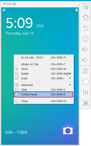
The control keys are visible on the emulator when you start it. To access the context menu, right-click the emulator.
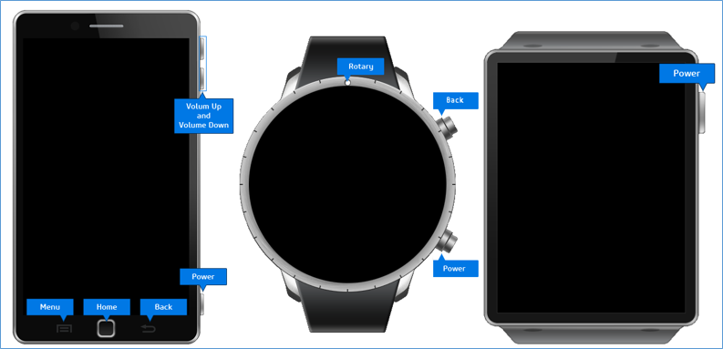
Figure: Emulator control keys
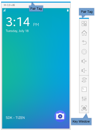
The emulator can use a general purpose or profile-specific skin. While the profile-specific skin provides a realistic skin and hardware keys, the general purpose skin shows a consistent frame on every state of resolution, scale, or rotation, and enables you to change the emulator display resolution to custom values. You can also see the key window.
- Key window
The key window consists of virtual hardware keys, which are embedded in profile-specific skins. You can use it as a remote controller of its main emulator window. You can move it to any position separate from the main window, or dock it to the right side of the main window. If it is docked with the main window, both windows can be moved together on the screen.
You can make the key window appear or disappear through the context menu or a shortcut key.
- Pair tag
The color of the pair tag indicates which main window is paired with which key window. The color changes every time the emulator boots.
The following figure illustrates the general purpose skin emulator.
Figure: General purpose skin emulator
Control Keys
The following hardware keys are available on the emulator:
- Menu (mobile only)
When tapped, a list of options available for the current screen opens.
- Home (mobile only)
When long-pressed, the Task switcher application opens as on a real device.
- Back
When tapped, the emulator returns to the previous screen.
- Power
You can power off the display by tapping the Power key in most situations. Sometimes, the display does not power off when you tap the Power key. This is to guarantee the operation of a current application, such as the Stopwatch in the Clock application. If you tap the Power or Home key again, the display is powered on.
- Volume Up and Volume Down (mobile only)
When tapped, the volume changes accordingly.
Context Menu
You can access the context menu by right-clicking on the emulator. In the menu, you can select:
- Emulator name (the top row in the menu)
The Detailed Info window is displayed, showing the Shortcut Info and VM Info tabs. The Shortcut Info tab lists the emulator keyboard shortcuts and the VM Info tab defines the virtual machine details.
In macOS: To use the emulator keyboard shortcuts, open the Keyboard Setting dialog and switch your macOS function keys option to work as standard function keys.
Table: VM Info
Feature Description VM Name VM name Skin Name Skin name CPU Arch CPU architecture RAM Size RAM size (in MB) Display Target display resolution (in DPI; Dots Per Inch) Network Connection NAT (Network Address Translation) or Bridged CPU Virtualization Whether hardware virtualization is supported GPU Virtualization Whether GPU virtualization is supported Platform Image Version Version of the used platform image Platform Image File Location of the used platform image Directory Sharing Whether host directory sharing is used File Shared Path Path to the shared host directory Kernel Log File Kernel log file path Emulator Log File Emulator (Qemu) log file path Emulator Version Tizen Studio version - Always On Top
Select this option to keep the emulator window on top of other windows.
- Rotate
Select either Portrait, Landscape, Reverse Portrait, or Reverse Landscape as the orientation of the emulator.
- Scale (mobile only)
Scale the size of the emulator between 1x, 1/2x (default), 3/4x, and 1/4x.
- Advanced > Controller
Show or hide the controller window.
Note The Controller menu is not supported in the profile-specific skin. - Advanced > Screenshot
Capture a screenshot of the emulator.
- Advanced > About
Display the emulator version and build time.
- Advanced > Force Reboot
Force the emulator to reboot. Since force rebooting the emulator can cause problems, use the reboot option from the SDB shell to reboot the emulator. Use Force Reboot only when absolutely necessary.
- Advanced > Force Close
Force the emulator to exit. Since force stopping the emulator can cause problems, use the Close option to exit the emulator. Use Force Close only when absolutely necessary.
- Shell
Open a Smart Development Bridge (SDB) shell command window.
- Control Panel
Control or monitor the state of the emulator dynamically.
- Close
Exit the emulator.
- In the command console, execute the
gconf-editorcommand. - In the tree, navigate to
desktop > gnome > interface. - Enable the
menus_have_iconsoption.
Using the Control Panel
With the Emulator Control Panel, you can simulate system events and perform related tasks.
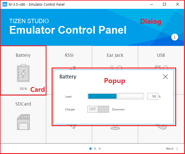
The control panel consists of 3 layers:
- Dialog is the main Emulator Control Panel window, which shows a list of testable device cards.
- Card represents a peripheral device or system option, and shows the respective device or option status. By clicking a card, you can simulate an event directly or open a Popup to do it.
- Popup displays testable events for a peripheral device.
Figure: Emulator Control Panel
To open the control panel:
- Launch the emulator.
- Right-click the emulator and select Control Panel.
The following table lists the control panel features and their availability on different profiles. The instructions for using the features are described below the table. You can use various keyboard shortcuts for control panel tasks.
Table: Control panel features
| Feature | Mobile | Wearable | Description | |
|---|---|---|---|---|
| Network | Yes | Yes | You can control the user network and forward a remote or local port to an inside port of the emulator. | |
| Host Directory Sharing | Yes | Yes | You can transfer files through the host directory sharing feature without using the SDB utility. | |
| App Manager | No | Yes | You can see user-installed applications and uninstall them. | |
| Battery | Yes | Yes | You can set the battery level and charger status. | |
| RSSI | Yes | No | You can set the remote signal strength. | |
| Sensor | 3-Axis | Yes | Yes | You can simulate user acceleration, magnetic, and gyroscope values. |
| Light | Yes | Yes | You can simulate a lux value for the light sensor. | |
| Proximity | Yes | Yes | You can simulate the presence of nearby objects. | |
| Pressure | Yes | Yes | You can simulate an hPa value for the pressure sensor. | |
| Ultraviolet | Yes | Yes | You can simulate an ultraviolet index value. | |
| Heart Rate Monitor | Yes | Yes | You can simulate the user heart rate and peak-to-peak time. | |
| Pedometer | Yes | Yes | You can simulate user movement with the device. | |
| Earjack | Yes | No | You can add or remove a headset. | |
| USB | Yes | Yes | You can add or remove a USB device. | |
| SD Card | Yes | No | You can simulate a 4G, 8G, 16G, or 32G SD card. | |
| NFC | Yes | Yes | You can simulate near-field communication (NFC) events. | |
| Location | Yes | Yes | You can simulate latitude and longitude values using a map, manually, or from a log file. | |
| Telephony | Yes | Yes | You can make and receive a call. You can also send and receive SMS messages. | |
| Memory | Yes | Yes | You can set the memory status. | |
Controlling the Network Setting
In the Network card, you can control the user network.
To lose the network connection, set the Link Status switch off. To forward a remote or local port to an inside port of the emulator, enter values in the text boxes, and click Apply.
Mounting a Host Directory
In the HDS card, you can configure host directory sharing (HDS) to share resources and transfer files without using the SDB utility. The specified host directory is mounted to /mnt/host.
Uninstalling Applications
In the App Manager card, you can view a list of user-installed applications and uninstall them.
Providing Device Data
The control panel can be used to simulate various device data:
- In the Battery card, you can set the battery level using the Level slider. You can also connect or disconnect a charger using the Charger switch.
- In the Ear Jack card, you can add or remove an earjack (headset) device. You can add a 3-wire or 4-wire device.
- In the USB card, you can connect or disconnect a USB device.
- In the RSSI card, you can set the RSSI (remote signal strength indicator) information level.
- In the SDCard card, you can attach or detach an SD card to or from the emulator at runtime. You can attach a 4G, 8G, 16G, or 32G SD card.
Note The same SD card cannot be attached to multiple emulators at the same time.
Device information set using the control panel is reflected on the indicator bar of the emulator screen.
Providing Location Data
In the Location card, you can provide simulated responses to location data requests:
- Injecting map markers
In the Map Image section, right-click the desired map locations and click Inject Markers to send the location data to the emulator.
- Manually entering location coordinates
In the Manual section, enter the coordinates and click Inject Location to send the location data to the emulator. The range of the latitude, longitude, altitude, and horizontal accuracy is from -90 to 90, -180 to 180, -300 to 100000, and 0 to 100000, respectively.
- Loading a GPS log file
In the Log section, select a pre-logged GPS data file (in NMEA183 format) and click Inject Log to send the location data to the emulator.
Providing NFC Data
In the NFC card, you can test near-field communication (NFC) features.
- Creating NFC data exchange format (NDEF) messages
An NDEF message contains 1 or more NDEF records. In the NDEF Message section:
- Select the record type name format.
- Enter the record type name, ID, and payload.
- Click Add.
You can add multiple NDEF records in the NDEF message.
Click Edit or Remove to modify or delete a selected record.
- Attaching and detaching NFC tags
In the NDEF Tag section:
- Select the tag type.
- Click the switch to attach or detach the tag.
If the NDEF record list is not empty, an NDEF message is created using this list and the attach message is sent to the emulator with the NDEF message.
- Creating a peer-to-peer (P2P) data connection
In the PEER TO PEER section:
- To inform the emulator that a new device has been discovered, click P2P Discovered.
- To send the emulator an NDEF message, click P2P Send.
- To inform the emulator that a connected device has been detached, click P2P Detached.
Providing Sensor Data
In the control panel, you can model user actions, such as shaking, throwing, and tilting the device, for the emulator instance. In addition, you can simulate a single sensor event on the instance, or send sequences of 3-axis sensor events to the instance.
- In the Sensor card, you can control the 3-axis sensors. The popup consists of 4 tabs, where you can adjust the acceleration, magnetic, and gyro sensors of the emulator instance. In the GUI tab, you can intuitively adjust various sensor data by using 3D graphics.
- GUI
In the GUI tab, you can select an active sensor and move the 3D model of the emulator instance with the 3 axis sliders or the direction buttons (Portrait, Landscape, Reverse Portrait, and Reverse Landscape). The instance monitor displays the acceleration, magnetic, and gyro values.
To better control the movement, select the With axis checkbox to see the axes in the emulator image. You can also fix the Y or Z axis by selecting the X/Z or X/Y radio button, respectively. To change the emulator accelerator value in the direction of the movement, select the Move radio button.
- Acceleration
In the Acceleration tab, you can control the acceleration of the instance along the coordinate axes. When the emulated device is stationary and vertical in portrait orientation, the acceleration value of the Y axis is 1 g (gravitational acceleration). You can control the acceleration 3-axis values from -2 g to 2 g, using the sliders.
- Magnetic
In the Magnetic tab, you can control the magnetic field values of the instance along the coordinate axes. When the emulated device is stationary and vertical in portrait orientation, the Y axis is at true north and the magnetic field strength values are 1, 0, and -10 µT (microtesla). You can control the magnetic field 3-axis values from -2000 µT to 2000 µT, using the sliders.
- Gyro
In the Gyro tab, You can control the gyro (rotation angle per second) of the instance along the coordinate axes. You can control the gyro 3-axis values from -573 degrees/s to 573 degrees/s, using the sliders.
You can simulate a single event on the individual sensor, or use sensor data files to simulate sequences of events on the sensor. A sensor data file consists of predefined events. It is written in ASCII. By loading a data file in the Acceleration, Magnetic, or Gyro tab, you can play a sequence of predefined events. You can also add multiple data files to be played in sequence. The format of each line in the event file is:
timestamp, x, y, z
When you add the event files and click Start, the predefined events are simulated at their specified relative timestamp. The timestamp unit is 0.01 seconds. Some events can be discarded, if they exceed certain limits of performance, resource, or logic.
- GUI
- In the Light card, you can simulate ambient light conditions using the Lux slider. The range of this value is from 0 Lux to 65635 Lux.
If automatic screen brightness is activated in the device settings, the display changes based on the simulated light value.
- In the Proximity card, you can set the proximity sensor state to Far or Near.
- In the Pressure card, you can control the pressure sensor using the hPa slider. The range of this value is from 260 hPa to 1260 hPa (hectopascals).
- In the Ultraviolet card, you can control the ultraviolet sensor using the Index slider. The unit is UV index and the range of this value is from 0 to 15.0.
- In the Heart Rate card, you can control the HRM (Heart Rate Monitor) sensor. You can use the bpm slider to set the heart rate value between 0 and 220 bpm, and the ms slider to set the peak-to-peak time between 0 and 5000 ms (milliseconds).
- In the Pedometer card, you can simulate user movement with the device by selecting a movement pace:
- Stop
- Walk Slowly
- Walk
- Run Slowly
- Run
Providing Telephony Features
In the Telephony card, you can generate incoming calls and messages:
- Generating incoming calls
Incoming calls are generated in the Call tab.
Note A Mobile Termination (MT) call is made from the Emulator Control Panel to the emulator. A Mobile Origination (MO) call is made from the emulator to the Emulator Control Panel using the emulator's phone application.To make an MT call:
- In the MT Call section, enter the phone number you want to imitate the call from.
- Click Connect.
- To hide the phone number on the emulator, select the Hidden option.
The caller ID on the emulator is set to "Unknown".
To make an MO call:
- Call a phone number using the emulator's phone application.
In the MO Call section, you can see the call ID, number, and call type.
- To disconnect the call, click Disconnect.
- Generating messages
SMS messages are generated in the Messaging tab. After sending a message, your application waits for the asynchronous send status message. You can generate this status report for SMS messages using the same Messaging tab.
To generate an SMS message:
- Enter the sender phone number you want to imitate.
- Enter the message body text and click Send Msg.
To generate status reports, select the sending status value for the SMS message and click Set. The available values are:
- SMS OK(Success)
- SMS Not Available
You can also generate MMS message status reports. To generate MMS status reports, select the sending status value for the MMS message and click Set. The available values are:
- MMS OK(Success)
- MMS Failure
Providing Memory Data
In the Memory card, you can select a specific memory status using the radio buttons:
- Hard Warning (40 MB and under)
- Soft Warning (60 MB and under)
- Normal (Sufficient)
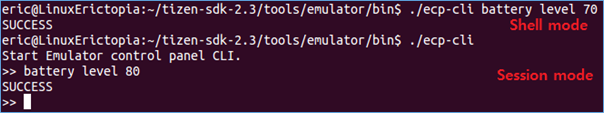
Controlling the Control Panel from the Command Line
You can control and monitor the Tizen Emulator by using the Emulator Control Panel CLI instead of the control panel UI tool. The CLI supports all the functionalities of the UI. The CLI binary is located in:
- Ubuntu:
<TIZEN_STUDIO>/tools/emulator/bin/ecp-cli - Windows®:
<TIZEN_STUDIO>\tools\emulator\bin\ecp-cli.bat
You can use the CLI in a session mode or shell mode:
- Session mode
You can access this mode by running the binary without any parameters. The mode keeps a session until it is exited. You can exit by entering the
exitcommand. - Shell mode
This mode is used for one-time message handling.
Figure: Session and shell modes
In Ubuntu, the bash-based auto-completion is activated with the TAB key.
The following tables list the commands supported by the control panel CLI.
Table: CLI common commands
| Command | Syntax | Description |
|---|---|---|
help |
help [device] |
To get help, type the command as help. For a more specific device help, use the device parameter. |
keycode |
keycode <key-code> [period|press|release] |
To enter a key code for a mobile device:
|
hmp |
hmp <hmp command> |
Access the QEMU human monitor protocol commands. For a list of provided commands, enter the ecp-cli hmp help command. |
qmp |
qmp <qmp command> |
Access the QEMU monitoring protocol. The commands are handled in JSON format, and do not require {"execute": "qmp_capabilities"} to be in the control mode.
In the shell mode, the shell does not support the double quotation mark (") as an argument. For the JSON arguments, use \" (backslash + double quotation mark) instead. |
hds |
hds mount <host path> <guest path> |
Enable the host directory sharing feature between the specified <host path> and the emulator's <guest path>. The specified path must be a folder, not a file. |
hds unmount <id> |
Unmount the mounted host directory sharing path. The id is the HDS ID and you can get it from the hds status command. |
|
hds status |
Show the current host directory sharing status. |
Table: CLI profile commands
| Feature command | Sub-command | Mobile | Wearable | Syntax |
|---|---|---|---|---|
telephony |
call dial |
Yes | Yes | telephony call dial <number> |
call hidden-dial |
Yes | Yes | telephony call hidden-dial <number> |
|
call connect |
Yes | Yes | telephony call connect |
|
call disconnect |
Yes | Yes | telephony call disconnect <call id> |
|
sms send |
Yes | Yes | telephony sms send <number> <text> |
|
sms set |
Yes | Yes | telephony sms set <available | unavailable> |
|
sms status |
Yes | Yes | telephony sms status |
|
sms mms_status |
Yes | Yes | telephony sms mms_status |
|
location |
set |
Yes | Yes | location set <longitude> <latitude> |
status |
Yes | Yes | location status |
|
stop |
Yes | Yes | location stop |
|
file |
Yes | Yes | location file <file-path> |
|
battery |
level |
Yes | Yes | battery level <percent> |
charger |
Yes | Yes | battery charger <on | off> |
|
status |
Yes | Yes | battery status |
|
earjack |
set |
Yes | No | earjack set <3wire | 4wire | off> |
status |
Yes | No | earjack status |
|
usb |
set |
Yes | Yes | usb set <on | off> |
status |
Yes | Yes | usb status |
|
rssi |
set |
Yes | No | rssi set <0~4> |
status |
Yes | No | rssi status |
|
sdcard |
attach |
Yes | No | sdcard attach <sdcard_[ 4 | 8 | 16 | 32 ]G> |
detach |
Yes | No | sdcard detach <sdcard_[ 4 | 8 | 16 | 32 ]G> |
|
status |
Yes | No | sdcard status |
|
nfc |
tag attach |
Yes | Yes | nfc tag attach <tag type> <NDEF message> |
tag detach |
Yes | Yes | nfc tag detach |
|
p2p attach |
Yes | Yes | nfc p2p attach |
|
p2p send |
Yes | Yes | nfc p2p send <NDEF message> |
|
p2p detach |
Yes | Yes | nfc p2p detach |
|
status |
Yes | Yes | nfc status |
|
sensor |
accelerometer |
Yes | Yes | sensor accelerometer <x> <y> <z> |
gyroscope |
Yes | Yes | sensor gyroscope <x> <y> <z> |
|
magnetic |
Yes | Yes | sensor magnetic <x> <y> <z> |
|
proximity |
Yes | Yes | sensor proximity <value> |
|
light |
Yes | Yes | sensor light <value> |
|
pressure |
Yes | Yes | sensor pressure <level> |
|
uv |
Yes | Yes | sensor uv <level> |
|
hrm |
Yes | Yes | sensor hrm <level> |
|
pedometer |
Yes | Yes | sensor pedometer <state> |
|
status |
Yes | Yes | sensor status [sensor] |
|
file |
Yes | Yes | sensor file <sensor> <path> |
|
low_memory |
set |
Yes | Yes | low_memory set <hard-warning | soft-warning | normal> |
status |
Yes | Yes | low_memory status |