First Steps with Unity in Tizen - Part 2
PUBLISHED
Introduction
Some time ago we published the first part of this article series, which was focused on the configuration of both the Tizen SDK and Unity to be able to properly build and run applications on Tizen devices. The second part gives some general overview of the Unity Editor and describes how to prepare a sample application, which will be containing 3D objects.
Unity Editor - main components
In the previous article you were able to run the Unity environment and launch the application on a Tizen device. You just used the Unity Editor only for checking if you are able to launch the application. This time you will create one. But before you do that, you will get some overview about the components of the editor.
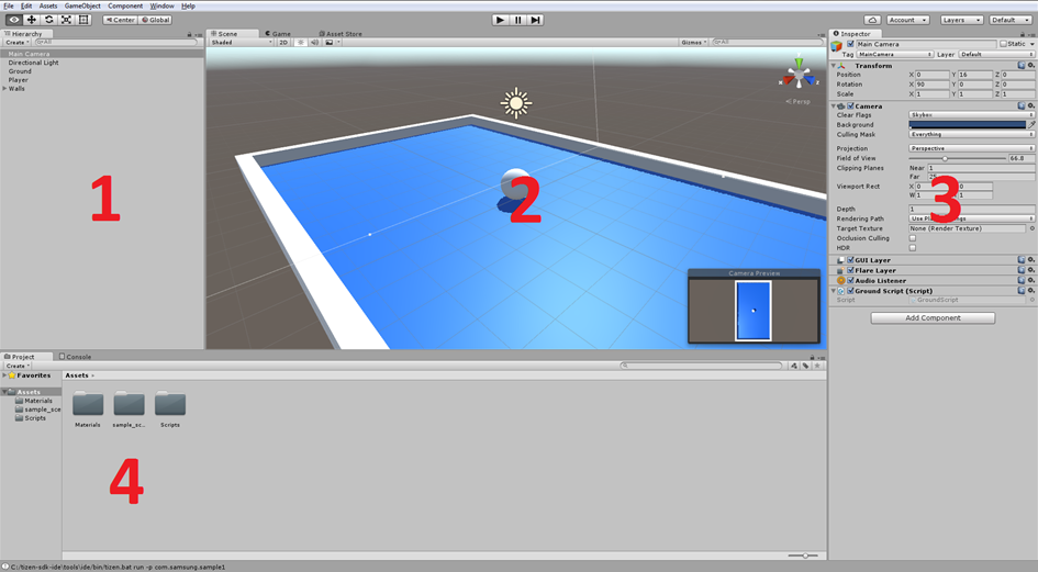
Figure 1. Unity Editor default layout
On the above figure you can see the default editor layout. If right now you have a different layout you can simply switch to the above one by choosing the proper menu item: Window -> Layouts -> Default. Of course you can customize the look of the layout as you wish by changing positions and sizes of proper items by a simple drag & drop operation or by adding new ones if you need. The default layout will help you in finding items enlisted on Figure 1:
- Hierarchy list – indicates objects or group of objects, which are used on the scene
- Scene/Game preview – shows the current look of the application from the chosen by the developer perspective (Scene tab) or the player (end user) perspective (Game tab)
- Inspector component – displays available options for the selected object from the Hierarchy list
- Assets list – shows the list of assets, for example materials, scenes or scripts
Adding and setting objects on the scene
After creation of a new scene (File -> New Scene) there are two objects available in the Hierarchy list: Main Camera and Directional Light.
To set properly a camera and other properties you have to understand how the coordinate system looks like in the Unity3D world. It is especially important in the case when you would like to use gravity in your game (we will use it in our sample application).
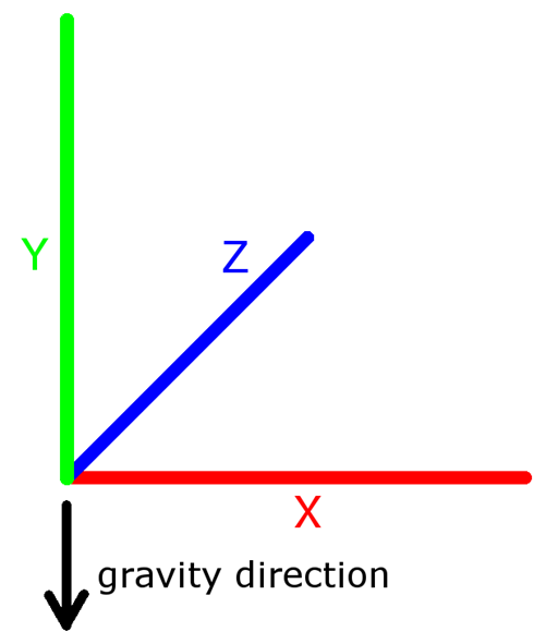
Figure 2. Unity3D coordinate system
As you can see on the above figure, x and z axes are like latitude and longitude and the y axis is like altitude, but of course expressed in other units. Thanks to this information it should be easier for you to understand how things work in Unity3D.
The first step in creating our application will be changing the Main Camera properties. To change this and any other object property you have to select a proper item from the Hierarchy list, then in the Inspector component you will see all properties, which you can change for the selected object. In our case we would like to achieve a camera view from above, so in this situation we have to change the Position value in the Y axis and Rotation in X, just like in the figure below. We also have to change some other settings like the Field of View and Clipping Planes to adjust the view to our desired game area.
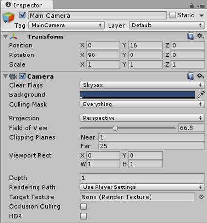
Figure 3. Properties of the Main Camera object in the Inspector tab
Now, when we have properly set the camera, we will create our first 3D object in our game area. To create a new object choose the Create menu in the Hierarchy component or GameObject in the upper window menu and select a proper object to add it. The first object will be the Plane object (Create -> 3D Object -> Plane). After adding the object it should be present in the Hierarchy list, where you can change its name using the F2 key (in our case the Plane object was renamed to “Ground”). Now we are ready to change properties of the Plane object the same way like it was made in the case of the Main Camera.
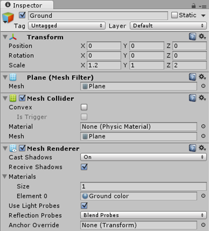
Figure 4. Properties for the Plane object in the Inspector
Of course the above property values are just for example purposes. It is highly recommended to play with the properties of each item to understand how things work. Starting from the basic ones like position, rotation and scale (the Transform group in the Inspector view). Additionally to change the color of our Ground we have to add a new item to our assets, which will be the Material. Simply click on the Create button in the Assets component and choose the Material item. You can name it as you wish and in the Inspector view you can choose a color using the Color picker tool.
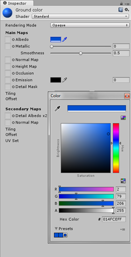
Figure 5. Editing Material color
When you want to choose a color of the Material asset then select the Ground object in the Hierarchy list and drag & drop the Material asset to the Inspector component of the Ground object. As the result you should see the Plane object in the chosen color. In more complicated projects it is worth to manage assets by creating catalogs like Materials, Scripts etc. and put there proper assets. You have to create a folder (menu Create -> Folder) and drop into it an asset. You can perform the same action in context of objects in the Hierarchy list by creating an Empty Child, which will serve as a container for the selected objects.
To see how it works in practice, we will create walls for our area and we will put them together in the same container. To create a wall we will use the menu Create -> 3D Object -> Cube and rename it to “Wall1”. It will be the upper wall, so we need to set it as shown on the figure below.
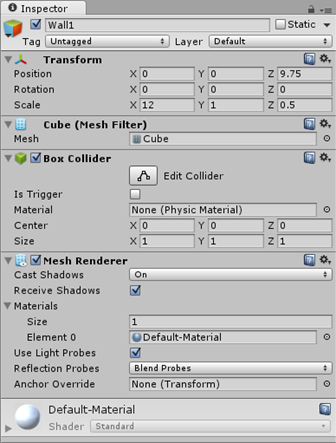
Figure 6. The First wall properties
To create the rest of the walls we can use the Duplicate feature, available after the right mouse click on a selected object in the Hierarchy list. Rename the created objects and set their properties to close up the sides of the earlier created ground area.

Figure 7. Properties of the other walls
Now, when we have all the walls set up we can put them to a common container. To do this you have to create an empty object (Create - > Create Empty), you can rename it and just drag & drop the previously created walls on it.

Figure 8. The Walls object containing four 3D objects
Now, when we have a fenced area we can add the last element, which will be a ball. To do this, we have to create a new 3D object which will be a sphere (Create -> 3D Object -> Sphere). We can rename it to “Player”, because it will be an object controlled by the user. How it will be controlled you will find out in the 3rd part of this article, but surely the gravity will play a key role here. Right now our ball is the only object permanently located and not reacting to any external forces. In order to make it possible for external forces to react on it, we have to add a physics component called the Rigidbody. It is very simple. Just go to the Inspection tab of the created sphere and click the Add Component button and then choose Physics -> Rigidbody. Or simply start typing “Rigidbody” into the search field and add it to the scene by pressing the Enter key. Please ensure that in the Rigidbody section of the Player object you have checked the Use Gravity property. You can also change the mass of the object. But please note that effects of this operation will be visible after applying changes from the third and last part of this article series.
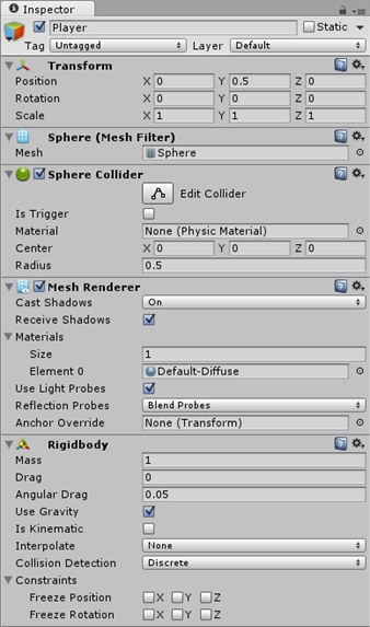
Figure 9. The Sphere (Player) properties
To see your work results on a Tizen device go to File -> Build Settings… menu and switch to the Tizen platform (you should already have done that in part 1 of this article). After this you have to click the Build and Run button. Then you can sit down comfortably, drink coffee and admire you work.
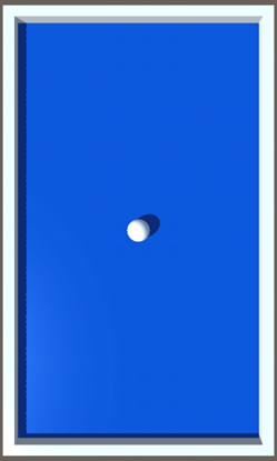
Figure 10. The final application look
Summary
After reading this article you should know how to add basic objects to the Unity3D scene and how to configure them. For the time being nothing is happening on the scene, but remember this is just the second article in our three article Unity3D series. Stay tuned for the last part. Meanwhile you can freely add new objects, experiment with their properties to better understand how the Unity Editor works. You can also watch more trainings on the Learn with Unity official website.