Custom 3D graphics on Tizen
PUBLISHED
The aim of this article is to familiarize the developer with Box2d and WebGL and describe how to use these external libraries in Tizen applications. These topics are illustrated with a sample application – Boules game.
This article shows how to add and use Box2dWeb in your Tizen web applications. We explain the library basics: creating the canvas, the world, static and dynamic objects. You will also learn how to simulate the physics world in debug mode. The second part of this article explains basics of WebGL on a HTML5 Canvas. You will learn how to create 3D objects, texture them and draw in the render loop. Although the problems covered by this article are simple, we expect the target reader to have some basic knowledge of computer graphics.
1 Sample application and prerequisites
A sample game called “Boules” is provided to demonstrate the use of physics and graphics libraries. It uses Box2dWeb to simulate the physics world and WebGL to render the graphics. The sample application is based on the jQuery Mobile 1.2.0 framework, which allows you to create highly scalable web applications with an intuitive and coherent user interface. To be able to use the jQuery Mobile, your application must include the jQuery 1.8.0 library as well. The sample application was tested on Tizen SDK 2.1.0.
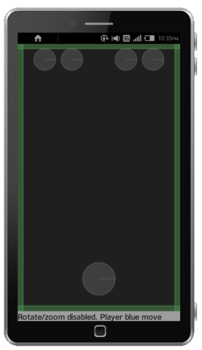
Main game view
The code samples use custom functions to send log messages to the console. They can be found in the application’s js/lib/internal folder.
2 Physics engine – Box2dWeb
Box2d is an open source C++ library for simulating rigid bodies in a 2D world. It is distributed under the zlib license. It has been ported to many different programming languages and environments including Java, Adobe Flash, C# and JavaScript.
There are two major open source Box2dWeb ports to JavaScript: Box2dJS (http://box2d-js.sourceforge.net/) and Box2dweb (http://code.google.com/p/box2dweb/). For our sample game we chose the second one, because it’s a more up to date port and it is stored in a single file.
You can find the documentation on http://code.google.com/p/box2dweb/. This is a documentation for Box2dFlash, but the Box2dWeb structure is organized similarly. That is because Box2dWeb is compiled from Box2dFlash and both JavaScript 1.6 and ActionScript 2.0 are based on the same ECMAScript standard. You may also find this tutorial useful: http://www.box2d.org/manual.html.
Box2dWeb is a physics engine. All the graphics in our sample application are generated by the WebGL, which will be explained in the second part of this article.
In the sample application we use a 2D graphics engine because the boules are moving only in two dimensions, on a flat area. WebGL is used for a more realistic view and to allow the user to change the view perspective.
Box2dWeb simulates rigid body movement and interactions including collisions and joints. The library also provides data that can be used to display the objects. It can simulate bodies composed of polygons, circles and edge shapes. Forces like gravity, friction and restitution (the force that makes objects bounce) can be applied to the objects.
Adding Box2dWeb to a Tizen application
To start using Box2dWeb in your Tizen application you have to import the library file into your project. The file also has to be declared in the index.html file:
<script type="text/javascript" src="./js/lib/external/Box2dWeb-2.1.a.3.min.js"></script>
You can now access Box2dWeb functions from your JavaScript files.
Create canvas
The canvas for Box2dWeb has to be defined in the index.html file:
<canvas id="canvas"></canvas>
You can set the width and the height of the canvas programmatically, so that it fits the screen:
var canvas = document.getElementById('canvas');
canvas.width = window.screen.availWidth;
canvas.height = window.screen.availHeight;
The window.screen.availHeight function returns the available screen height, without the top bar.
It is also a good idea to disable canvas scrolling. To do this you have to create a listener for touch move events and call the preventDefault() function on them:
canvas.addEventListener("touchmove", handleTouchMove, true);

function handleTouchMove(e) {
    e.preventDefault();
}
Create a Box2dWeb world
First, you have to create the Box2dWeb world object. It manages the memory, objects and simulation.
var world = new b2World(new b2Vec2(0, 0) // gravity
, true // allow sleep
);
The constructor takes two parameters: gravity and allowSleep. In the sample application we set the gravity vector to zero, because boules will be moving only on a flat area. The second parameter allowSleep determines whether to allow the bodies to go into the sleeping state when they come to rest. Simulating the bodies uses much of the devices’ resources, so when a body stops we want to pause simulating it and use the sleeping state, which has very little CPU overhead. The body is awakened when it collides with another body. You can also do it manually:
bodyDef.awake = true;
Create the ground
Box2dWeb bodies are the basic objects used by the library. You can define their position, shape and other parameters like friction or density. In our sample application we have a rectangular area for boules. It is limited by four rectangle objects.
To create a body, follow these steps:
- Create the body definition
For the ground we use static bodies:
var bodyDef = new b2BodyDef;
bodyDef.type = b2Body.b2_staticBody;
bodyDef.position.Set(0, 0);
- Define fixture
Fixtures attach shapes to bodies and add material properties such as density, friction and restitution. One fixture holds a single shape. A body can have many fixtures.
The following code sample shows how to create a fixture for the rectangle that limits the ground from the top. The other three rectangles are created in a similar way. The only changes are the width, height and position.
//create fixture object
var fixDef = new b2FixtureDef;

//define basic parameters
fixDef.density = 1.0;
fixDef.friction = 0.5;
fixDef.restitution = 0.2;

//scale for debug mode (it will be explained in the Setting debug draw section)
var SCALE = 30;

// canvas width and height in meters
var height = canvas.height / SCALE;
var width = canvas.width / SCALE;

var borderSize = height / 50;

//define shape
fixDef.shape = new b2PolygonShape;
fixDef.shape.SetAsBox(width, borderSize);
Polygon shapes can only be of the convex polygons. It means that every internal angle is less than or equal to 180 degrees and every line segment between two vertices remains inside or on the boundary of the polygon.
- Next, we set the body position, bind the fixture to the body definition and add the body to the world:
bodyDef.position.Set(0, 0);

world.CreateBody(bodyDef).CreateFixture(fixDef);
Create dynamic bodies
Now that we have already created the world and the ground, we can create the boules. We will use dynamic bodies for this.
var bodyDef = new b2BodyDef;
bodyDef.type = b2Body.b2_dynamicBody;
bodyDef.linearDamping = 1.0;
bodyDef.angularDamping = 1.0;
Damping is used to reduce the velocity of moving bodies. It should be between 0 and infinity. Linear damping influences linear velocity and angular damping reduces angular velocity.
The rest of the operations are exactly the same as for static bodies. For the boules we use a circular shape:
//radius of the main sphere, 1/10 of the screen width
var mainSphereRadius = width / 10;
fixDef.shape = new b2CircleShape(mainSphereRadius);
Box2dWeb bodies can store some additional user data. In the sample application we use it to keep the information about the current boules state in the game (active/idle). This additional information is passed to the WebGL engine during the render loop.
var sphereBody = world.CreateBody(bodyDef);
sphereBody.SetUserData(data); //in example application data is a number representing boule state
Setting debug draw
Box2dWeb doesn’t provide any functions for displaying bodies. It just calculates the position and the rotation of all the bodies. The view you see on Box2dWeb examples is created in the debug mode.
Debug mode
This mode can be used for debugging purposes. It is very useful in the development process because you can check whether the bodies look and act the way they should before attaching the graphics layer to them. In the sample application the debug mode can be switched on/off with a global debug variable in the main.js file.
var debugDraw = new b2DebugDraw();
debugDraw.SetSprite(document.getElementById("canvas").getContext("2d"));
debugDraw.SetDrawScale(30);
debugDraw.SetFillAlpha(0.5);
debugDraw.SetLineThickness(1.0);
debugDraw.SetFlags(b2DebugDraw.e_shapeBit | b2DebugDraw.e_jointBit);
world.SetDebugDraw(debugDraw);
The most important value from the sample code above is the scale value (here 30). Box2dWeb uses its own unit system. When rendering the graphic you need to convert it to pixel coordinates. The scale value of 30 means that 1 meter = 30 pixels.
Please keep in mind that all of the shape positions and sizes in the sample application are calculated relatively to the screen width and height.
Simulating the world
Box2dWeb refreshes positions and other parameters of the bodies in discrete points of time. It is done by a computational algorithm called an integrator, which solves physics equations. According to the Box2d manual games require refresh frequency equal to at least 60Hz (1/60 seconds). Additionally Box2dWeb uses a constraint solver. It solves all constrains in the simulation, one at a time. To do it correctly we need to iterate over all of the constrains a few times. The number of iterations is defined by two parameters: velocity iterations and position iterations. Increasing these values makes the calculations more accurate, but affects the performance. With these three values: the time step, velocity iterations and position iterations we can call the Box2dWeb Step() function:
world.Step(1 / 60, 10, 10);
|
TIP The Box2dWeb world uses MKS units: meters, kilograms and seconds. It works best when objects are the size of typical real world objects. Moving objects should be between 0.1 and 10 meters. Static objects can be up to 50 meters. |
Function syntax: world.Step(timeStep, velocityIterations, positionIterations);
The above values come from the demo distributed with the library. You can choose your own parameters.
We can now draw the debug data on the screen (if we are in debug mode):
world.DrawDebugData();
After each world step you should clear any forces you have applied to your bodies with the ClearForces function:
world.ClearForces();
Obtain the touched body
This article demonstrates only a part of the Box2dWeb API. For more functions and a more detailed description refer to the documentation or manual.
The user touches the screen in order to control the game. To get the body at any given coordinates you have to create a query to the b2World object:
var selectedBody;

/**
 * Get b2Body object that was touched
 * @param touchX x touch coordinate
 * @param touchY y touch coordinare
 * @returns Body, that was touched (b2Body object)
 */
function getBodyAtTouch(touchX, touchY) {
    var aabb = new b2AABB();
    aabb.lowerBound.Set(touchX - 1, touchY - 1);
    aabb.upperBound.Set(touchX + 1, touchY + 1);

    // Query the world for overlapping shapes.

    selectedBody = null;
    world.QueryAABB(getBodyCB, aabb);
    return selectedBody;
}

/**
 * Get body touched and save it to selectBody variable
 * @param fixture Touched fixture
 * @returns true if success, false otherwise
 */
function getBodyCB(fixture) {
    if (fixture.GetBody().GetType() != b2Body.b2_staticBody) {
        if (fixture.GetShape().TestPoint(fixture.GetBody().GetTransform(), new b2Vec2(touchX, touchY))) {
            selectedBody = fixture.GetBody();
            return false;
        }
    }
    return true;
}
To get the body that was touched we use the QueryAABB() method. It takes two arguments. The first one is a callback function with one parameter – the found fixture. In the second argument we pass the coordinates of the area we want to search. In this case it is just a single point, so we use a small search area (a square with the side length equal to 0,001). The query returns a fixture. We check if the fixture is not the ground body (if it’s not static) and get the b2Body object from it.
3 WebGL
You just learned that Box2DWeb is a physics engine, so besides it we need some graphical environment to display the shapes. We decided to use WebGL for that.
WebGL is a web standard that enables drawing and animating a 2D, 2.5D or 3D world on HTML5 Canvas elements. WebGL is based on OpenGL ES 2.0 and is very similar to it. Most of the functionalities from OpenGL ES 2.0 can be found in WebGL. Many useful functions can also be found in additional libraries that we used in the sample application. Developers that have experience with OpenGL will very quickly adapt to the new environment.
WebGL is a low-level, cross-platform API. It uses the shading language (GLSL), which processes commands directly in the GPU. As a result WebGL offers great performance and hardware-acceleration. On the other hand it is not that easy so we present it not going deeply into the details.
GLSL
GLSL is an OpenGL Shading Language. It is based on the C language and was created to give developers direct access to the graphics processing unit without using the assembly language.
In this article we will use an additional library called glMatrix v0.9.5. It provides a lot of useful functionalities, which make programming in WebGL much easier. The glMatrix library can be found here: http://code.google.com/p/glmatrix/
In the following sections you will learn how to set up the WebGL environment, create objects, load them to the WebGL buffers and draw them on the HTML5 Canvas.
Initializing WebGL on a HTML5 Canvas
To use a particular Canvas we need to get its context. The Canvas creates and exposes a fixed drawing surface. You can decide what kind of context you want to use. In our case it will be a WebGL 3D context: “experimental-webgl”. The Canvas also allows drawing the 2D context. To access the rendering context use the getContext() method, as follows:
canvas = document.getElementById('canvas');
gl = canvas.getContext("experimental-webgl");
After accessing the Canvas context we can take care of the shaders that will manage drawing on the canvas.
Setting shaders
In order to draw anything on the Canvas, WebGL needs two things:
- Clipspace coordinates
- Colors
Both of these parameters have to be passed to WebGL using shaders. As there are two things that WebGL requires to draw there are two shaders that deliver them.
- Vertex shader
The vertex shader takes care of vertices. - Fragment shader
This shader colors pixels.
The simplest shaders can be defined in the following way:
<script id="vertex-shader" type="x-shader/x-vertex">
attribute vec2 aVertexPosition;

void main() {
  		gl_Position = vec4(aVertexPosition, 0, 1);
}
</script>

<script id="fragment-shader" type="x-shader/x-fragment">

void main() {
gl_FragColor = vec4(0,0,1,1);
}
</script>
Both of these shaders must be defined. The above code will just fill the whole Canvas with blue color. In order to draw some more complex 3D objects we will need to use the following shaders:
<script id="shader-vs" type="x-shader/x-vertex">
    attribute vec3 aVertexPosition;
    attribute vec3 aVertexNormal;
    attribute vec4 aVertexColor;
    attribute vec2 aTextureCoord;

    uniform mat4 uMVMatrix;
    uniform mat4 uPMatrix;
    uniform mat3 uNMatrix;

    varying vec2 vTextureCoord;

    void main(void) {
        gl_Position = uPMatrix * uMVMatrix * vec4(aVertexPosition,
     1.0);
        vTextureCoord = aTextureCoord;
    }
</script>

<script id="shader-fs" type="x-shader/x-fragment">
    precision mediump float;

    varying vec2 vTextureCoord;

    uniform sampler2D uSampler;

    void main(void) {
        gl_FragColor = texture2D(uSampler, vec2(vTextureCoord.s,
       vTextureCoord.t));
    }
</script>
The above shaders are more complex, but fortunately you do not need to know how they work in detail.
Shaders – the basics
Since WebGL is 2D we need to provide it with 2D coordinates and corresponding coloring. But later on everything is done in 3D, so how is this possible? The role of the vertex shader is to change all we do in 3D to 2D and pass it to WebGL. That is exactly what is happening in the shaders. We pass our 3D objects to shaders, they change them to 2D, color them and pass the result to WebGL to draw everything on the Canvas.
The instruction on how to change 3D to 2D is stored in the projection matrix (uPMatrix). Second important matrix is a model view Matrix (uMVMatrix). It stores all operation that we do on our objects. This means that if we move some object and scale some other the information about these operations will be stored in the model view matrix.
In conclusion we must provide shaders with our 3D objects, operations that we want to do on those objects and how we want shaders to transform these elements into 2D coordinates.
Initializing shaders
Now that the shaders are set, we need to pass their code to the WebGL so that they can be compiled. It can be done in the following way:
var vertexShader = gl.createShader(gl.VERTEX_SHADER);
gl.shaderSource(vertexShader, str);
gl.compileShader(vertexShader);
and fragment shader:
var fragmentShader = gl.createShader(gl.FRAGMENT_SHADER);
gl.shaderSource(fragmentShader, str);
gl.compileShader(fragmentShader);
The str variable that is passed to the shaderSource function, must contain a proper shader implementation, which we just described in the previous section.
In WebGL shaders are handled using a shader program. We must create this program and link our compiled shader to this program. Without the shader program shaders will not work. Here is a sample code showing how to do this (please refer to the http://learningwebgl.com blog):
var fragmentShader = getShader(gl, "shader-fs");
var vertexShader = getShader(gl, "shader-vs");

shaderProgram = gl.createProgram();
gl.attachShader(shaderProgram, vertexShader);
gl.attachShader(shaderProgram, fragmentShader);
gl.linkProgram(shaderProgram);

if (!gl.getProgramParameter(shaderProgram, gl.LINK_STATUS)) {
    alert("Could not initialise shaders");
}

gl.useProgram(shaderProgram);
As mentioned before, in order to draw something more complex we need to provide shaders with objects’ coordinates, colors (or textures), a projection matrix and a model view matrix. This can be done by creating some sort of bridge between JavaScript variables and shaders variables. The following code snippet is responsible for transporting data from JavaScript variables to the shaders variables.
shaderProgram.vertexPositionAttribute =
gl.getAttribLocation(shaderProgram,"aVertexPosition");
gl.enableVertexAttribArray(shaderProgram.vertexPositionAttribute);

shaderProgram.textureCoordAttribute =
gl.getAttribLocation(shaderProgram, "aTextureCoord");
gl.enableVertexAttribArray(shaderProgram.textureCoordAttribute);

shaderProgram.vertexColorAttribute =
gl.getAttribLocation(shaderProgram, "aVertexColor");
gl.enableVertexAttribArray(shaderProgram.vertexColorAttribute);

shaderProgram.pMatrixUniform =
gl.getUniformLocation(shaderProgram, "uPMatrix");
shaderProgram.mvMatrixUniform =
gl.getUniformLocation(shaderProgram, "uMVMatrix");
shaderProgram.nMatrixUniform =
gl.getUniformLocation(shaderProgram, "uNMatrix");
shaderProgram.samplerUniform =
gl.getUniformLocation(shaderProgram, "uSampler");
WebGL is now started and shaders are loaded.
We can now proceed to object creation. Before any object can be drawn, it must be created. Creating an object in WebGL means defining its vertices, indexes and colour or texture coordinates. All these parameters must be passed to the WebGL buffers. Then every time we want to draw an object we need to set these buffers as active to tell WebGL that we want to draw this specific object.
Creating objects in WebGL
Below we describe how to create a simple WebGL object – a cuboid. It will be the ground object for the Boules game.
To create an object you have to:
1. Define vertices
In WebGL coordinates range from -1 to 1. This means that every object’s vertices’ coordinates must be between -1 and 1. This is not a problem because later on we scale every object to the size that fits our needs.
The ground vertices are as shown in the picture.
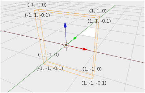
Cuboid coordinates
Please note that the x axis is red, the y axis is blue and z is green. This coordinate system is exactly the same as in OpenGL ES.
There are 8 vertices so the vertices array should look like this:
var vertices = [
    -1.0, -1.0,  0.0,
     1.0, -1.0,  0.0,
     1.0,  1.0,  0.0,
    -1.0,  1.0,  0.0,

    -1.0, -1.0, -0.1,
     1.0, -1.0, -0.1,
     1.0,  1.0, -0.1,
    -1.0,  1.0, -0.1,
];
We now need to transform this array to a buffer and link it to the WebGL:
groundVertexPositionBuffer = gl.createBuffer();
gl.bindBuffer(gl.ARRAY_BUFFER, groundVertexPositionBuffer);
gl.bufferData(gl.ARRAY_BUFFER, new Float32Array(vertices), gl.STATIC_DRAW);
groundVertexPositionBuffer.itemSize = 3;
groundVertexPositionBuffer.numItems = 8;
2. Connect the vertices
Vertices need to be properly connected to each other to form an object. Since the basic shapes drawn by WebGL are triangles, all the objects must be created from triangles. These triangles create the faces of a cuboid. With easy calculations we define 12 triangles and create an array that will store their coordinates:
var cubeVertexIndices = [
    0, 1, 2,      0, 2, 3,
    0, 4, 3,      4, 7, 3,
    0, 4, 1,      1, 5, 4,
    1, 5, 6,      1, 6, 2,
    3, 7, 2,      2, 6, 7,
    7, 4, 6,      6, 4, 5
];
Each number in the above array is an index of the previously defined vertices array. So the first triangle will be created from 0, 1 and 2 vertices. The second triangle will be created from 0, 2 and 3 vertices and so on. Here is an image that shows the cuboid vertices indexes.
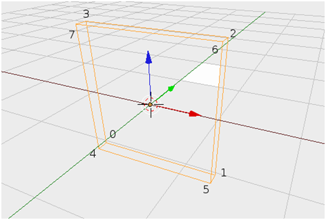
Indexes of vertices in cuboid
We now create a buffer and link it to WebGL:
groundVertexIndexBuffer = gl.createBuffer();
gl.bindBuffer(gl.ELEMENT_ARRAY_BUFFER, groundVertexIndexBuffer);
gl.bufferData(gl.ELEMENT_ARRAY_BUFFER, new Uint16Array(cubeVertexIndices), gl.STATIC_DRAW);
groundVertexIndexBuffer.itemSize = 1;
groundVertexIndexBuffer.numItems = 36;
3. Texturing the objects
With vertices and indexes defined we could draw the cuboid, but it would be colorless. In order to create textures we define texture coordinates so that the fragment shader will know where to draw the texture. Each vertex must have its own texture coordinate. A texture is a 2D image. This means that each vertex will have a (x, y) coordinates pair that corresponds to the texture point. Since our cuboid will simulate the ground we need to stretch the grass texture through two top triangles and two bottom triangles. Please refer to the code below:
var textureCoords = [
  0.0, 0.0,
  1.0, 0.0,
  1.0, 1.0,
  0.0, 1.0,

  0.0, 0.0,
  1.0, 0.0,
  1.0, 1.0,
  0.0, 1.0,
];
At the game start the cuboid face limited by points 4, 5, 6 and 7 will be a visible ground to the user. All boules will be placed on this face. That is why the texture must be stretched through these points and the texture coordinate ranges from 0,0 in point 4 to 1,1 in point 6.
You should create a buffer based on the coordinates and link it to WebGL:
groundVertexTextureCoordBuffer = gl.createBuffer();
gl.bindBuffer(gl.ARRAY_BUFFER, groundVertexTextureCoordBuffer);
gl.bufferData(gl.ARRAY_BUFFER, new Float32Array(textureCoords), gl.STATIC_DRAW);
groundVertexTextureCoordBuffer.itemSize = 2;
groundVertexTextureCoordBuffer.numItems = 4;
Unfortunately we did not load the file texture yet. We’ll do it now (for more details please refer to http://learningwebgl.com):
var texture = gl.createTexture();
texture.image = new Image();
texture.image.onload = function() {
  handleLoadedTexture(texture)
}

texture.image.src = "images/Grass.jpg";
When the image is loaded the handleLoadedTexture() is called. You can refer to the code below:
var handleLoadedTexture = function (texture) {
    gl.bindTexture(gl.TEXTURE_2D, texture);
    gl.pixelStorei(gl.UNPACK_FLIP_Y_WEBGL, true);
    gl.texImage2D(gl.TEXTURE_2D, 0, gl.RGBA, gl.RGBA, gl.UNSIGNED_BYTE, texture.image);
    gl.texParameteri(gl.TEXTURE_2D, gl.TEXTURE_MAG_FILTER, gl.NEAREST);
    gl.texParameteri(gl.TEXTURE_2D, gl.TEXTURE_MIN_FILTER, gl.NEAREST);
    gl.bindTexture(gl.TEXTURE_2D, null);
  };
After loading the texture file we need to link the texture reference with WebGL. After doing so we can set the texture as active. Since vertices, indices and texture coordinates are already loaded to WebGL and the texture image is loaded and linked the creation of the ground object is finished.
Unfortunately, the ground object cannot be drawn right away as WebGL doesn’t know what we want to draw.
Drawing the object
The last command before drawing is setting the object’s buffers as active. We do this using the code below:
gl.bindBuffer(gl.ARRAY_BUFFER, groundVertexPositionBuffer);
gl.vertexAttribPointer(shaderProgram.vertexPositionAttribute, groundVertexPositionBuffer.itemSize, gl.FLOAT, false, 0, 0);

gl.bindBuffer(gl.ARRAY_BUFFER, groundVertexTextureCoordBuffer);
gl.vertexAttribPointer(shaderProgram.textureCoordAttribute, groundVertexTextureCoordBuffer.itemSize, gl.FLOAT, false, 0, 0);

gl.activeTexture(gl.TEXTURE0);
gl.bindTexture(gl.TEXTURE_2D, texture);
gl.uniform1i(shaderProgram.samplerUniform, 0);

gl.bindBuffer(gl.ELEMENT_ARRAY_BUFFER, groundVertexIndexBuffer);
We now need to call the last method to actually draw the elements:
gl.drawElements(gl.TRIANGLES, groundVertexIndexBuffer.numItems, gl.UNSIGNED_SHORT, 0);
The code above will force WebGL to draw active buffers, that we have already set.
Unfortunately this is not enough to draw anything on the canvas. This is because in the 3D world WebGL requires setting some other parameters, like the perspective or model view and projection matrices.
We will use one additional library to help us out with these settings. glMatrix is a fast library that handles matrix operations very well.
WebGL settings
There are a few important parameters you have to set:
- Set background color for the canvas. This method will clear the canvas and fill it with the user specified RGB color. The last parameter is transparency.
gl.clearColor(0.0, 0.0, 0.5, 0.5);
- Enable buffer depth:
This will actually add the z axis. Normally WebGL draws elements on each other. This means that the last drawn element will be drawn on top of everything, regardless of its z coordinate. When we enable the depth buffer we tell WebGL to take the z parameter into consideration. As a result objects that are closer to the camera will be drawn on top of the others.
gl.enable(gl.DEPTH_TEST);
- Set the WebGL size:
gl.viewport(0, 0, gl.viewportWidth, gl.viewportHeight);
- Clear color and depth buffers
In every rendering iteration the color and depth buffers must be cleared to display the 3D world properly. Otherwise the trace of the previously drawn objects will remain and will be displayed on the canvas.
gl.clear(gl.COLOR_BUFFER_BIT | gl.DEPTH_BUFFER_BIT);
Perspective and frustum
You can create and load as many objects as you like. Furthermore you can specify its positions and tell WebGL to draw them on the screen. Still WebGL will only draw what is visible from the camera perspective, leaving objects that are out of the view scope unrendered and will not waste time and resources for them. That is why you have to specify the WebGL’s frustum using perspective method. Please refer to the below image to see what the frustum is:
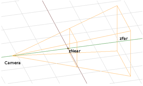
WebGL frustum
Frustum is the right part of the pyramid between zNear and zFar. The camera is on the left. Using the perspective() method you set the two mentioned variables (zNear and zFar) and the angle of the pyramid. Now if you want to make your objects visible we must place them in this frustum, otherwise they will not be taken into account when rendering the Canvas screen.
Below you can find the perspective built for the Boules game:
mat4.perspective(45, gl.viewportWidth / gl.viewportHeight, 0.1, 100.0, pMatrix);
The 45 value is the pyramid angle and 0.1 and 100.0 are zNear and zFar settings. This means that only objects with z coordinates between 0.1 and 100.0 will be drawn on the screen. As described previously pMatrix is a projection Matrix responsible for changing a 3D scene to a 2D one. This is because WebGL essentially works in a 2D space and we need to create the 3D illusion using perspective. By creating projection matrix with perspective method we provide information to shaders how to perform the 3D to 2D transformation.
Translation and rotation
The simplest and most basic operations that we can perform on objects are translation and rotation. They are used to move and change object size in WebGL. All the operations that will be performed on objects must be stored in a model view matrix that will later be used by the shaders. This means that each operation is saved to a matrix. The simplest approach to do that is by starting with an identity matrix. The identity matrix is a matrix that does not influence any object.
mat4.identity(mvMatrix);
Moving and rotating is done as follows:
mat4.translate(mvMatrix, [0, 0, -4]);
mat4.rotateX(mvMatrix, tiltAngle);
mat4.rotateZ(mvMatrix, twistAngle);
In order to translate something we must pass a vector with a shift in the x, y and z axis.
As you can see we do not specify any reference to the object that we want to draw. This is why we have to set some buffers to be in the active state and WebGL will use them to draw the object. Another important thing is that we do not use coordinates to tell WebGL where to draw, but we move the camera in the 3D space and WebGL draws them from the perspective of the current camera position. So if we want to draw the next element closer to the beginning of the z axis you have to use the translate() method with a positive z value.
There also is a function that can scale the object:
mat4.scale(mvMatrix, [1, gl.viewportHeight/gl.viewportWidth, 1]);
Using this function with the ground object will scale the ground object to fit the screen size.
As you can see a reference to the model view matrix is passed in each of these functions. Thanks to that all the operations that we just did will be saved directly to the mvMatrix. Just as described previously, mvMatrix will be used in shaders.
4 WebGL interface provided for the Box2DWeb
Until now we have described the Box2D physics engine and WebGL, the drawing environment. The last thing to do is to connect them. In our Boules game we took the approach where WebGL provides simple methods for displaying elements and Box2D uses those methods to draw.
We decided to completely separate the WebGL drawing functionality from the game logics. As a result the webgl.js module in the Boules application was created. It provides the following methods:
- webGLStart(canvas)
This method initializes WebGL on the referenced canvas.
Calling this method is sufficient to configure the Canvas for drawing. This method is responsible for all the shaders configuration we described at the beginning of the WebGL section. - initSphere(radius, sphereType)
Creates a sphere in WebGL with a specified type. In this function the sphere vertices and indexes are created and the proper texture is loaded. This function is responsible for all that was described in the “Creating objects in WebGL” paragraph. - drawScene(sphereData, distance, tiltAngle, twistAngle)
This function is used for the WebGL settings, like perspective. It also draws all the previously created spheres on the position provided in the sphereData variable.
The operations that are performed in this function have been described in the following sections: “WebGL settings”, “Perspective and frustum”, “Drawing object” and “Translation and rotation”.
The rendering loop is done by Box2D in the update function in game.js module. After each physics calculation Box2D calls the update function. This function updates the spheres’ positions and the distance between the camera and the board. These parameters are passed to the drawScene method. When the drawScene method is called a new frame is drawn on the Canvas.
5 Game rules
The game is based on the popular game of Boules: http://en.wikipedia.org/wiki/Boules . The goal of the game is to place the user's boules as near to the target boule (jack) as possible.
Start:
Every player has two boules in one colour. They are placed along the shorter edge of the screen. The jack (target boule) is placed on the opposite side of the screen.
Play:
- Players move their boules in turns. After moving the boule the user can zoom and rotate the board. To start the next player’s turn he/she has to tap the screen.
- Each player has three moves
- You can move any of the boules during your turn (for example the player can move one boule 3 times and leave the other in its original position, or move one boule 2 times and the other once)
- Players can only move their own boules
- The jack can be moved only when hit by another boule
- The speed of the ball depends only on the move vector length (and not on how fast you swipe your finger)

Player’s move
The End:
The distance between the jack and the player's boules is calculated. The player, whose boules are closer to the jack wins. After the game is finished the results are displayed on a separate page.
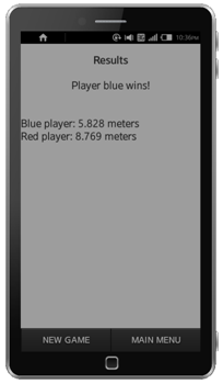
Results screen
6 Summary
This article describes how to use the Box2dWeb physics engine and WebGL graphics engine to create Tizen applications. You can use these libraries to create highly interactive games for Tizen. This article also shows that physics in mobile applications can be handled by external libraries enabling the developer to focus on application logic and user interface.