Shape Drawing
PUBLISHED


Dependencies
- Tizen 3.0 and Higher for Mobile
- Tizen 3.0 and Higher for Wearable
Content
Related Info
DALi offers a low-level rendering API. Do not use it for building user interfaces – DALi UI controls must be used instead. For example, if you need to display an icon, you can do it using the rendering API, but it requires a lot more effort than simply creating an ImageView UI control.
This topic shows how to use the rendering API through examples that draw a line, triangle, and cube.
Drawing a Line
To draw a line with the renderer API:
- Create the shader source code:
- You must create a shader suitable for drawing lines. The vector (x,y) position for each point on the line is passed using the
aPositionattribute. The vertex shader transforms this to match the size and position of an actor.const char* VERTEX_SHADER = DALI_COMPOSE_SHADER( attribute mediump vec2 aPosition; uniform mediump mat4 uMvpMatrix; uniform mediump vec3 uSize; void main() { mediump vec4 vertexPosition = vec4( aPosition, 0.0, 1.0 ); vertexPosition.xyz *= uSize; gl_Position = uMvpMatrix * vertexPosition; } ); - The fragment shader applies the actor’s color:
const char* FRAGMENT_SHADER = DALI_COMPOSE_SHADER(
  uniform lowp vec4 uColor;
  void main()
  {
    gl_FragColor = uColor;
  }
);
- You must create a shader suitable for drawing lines. The vector (x,y) position for each point on the line is passed using the
- Create geometry.
Specify a vertex format matching the shader attributes: the format is specified using a list of string/value pairs in a
Property::Map. The vertex format and data (in this case 2 points) are stored in aPropertyBuffer. Finally, aLINES-typeGeometryobject is created.Property::Map vertexFormat; vertexFormat["aPosition"] = Property::VECTOR2; PropertyBuffer vertices = PropertyBuffer::New( vertexFormat ); struct Vertex { Vector2 position1; }; Vertex vertexData[2] = { { Vector2( 0.5f, 0.5f) }, { Vector2( -0.5f, -0.5f) } }; const unsigned short INDEX_LINES[] = { 0, 1 }; vertices.SetData( vertexData, 2 ); Geometry geometry = Geometry::New(); geometry.AddVertexBuffer( vertices ); geometry.SetIndexBuffer( &INDEX_LINES[0], sizeof(INDEX_LINES)/sizeof(INDEX_LINES[0]) ); geometry.SetType( Geometry::LINES ); - Create a renderer.
You can create a renderer with the shader source and geometry. In order to position the renderer on-screen, it must be added to an actor which must be placed on the stage.
Shader shader = Shader::New( VERTEX_SHADER, FRAGMENT_SHADER );
Renderer renderer = Renderer::New( geometry, shader );

Stage stage = Stage::GetCurrent();
stage.SetBackgroundColor( Color::WHITE );

Actor actor = Actor::New();
actor.SetSize( stage.GetSize() );
actor.SetParentOrigin( ParentOrigin::CENTER );
actor.SetAnchorPoint( AnchorPoint::CENTER );
actor.SetColor( Color::BLACK );
actor.AddRenderer( renderer );
stage.Add( actor );
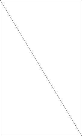
In this example, the line is rendered from one corner of the screen to the other.
Drawing a Triangle
To draw a triangle, use the same shader and renderer set-up as in the previous “Drawing a Line” example, and simply modify the geometry to draw the triangle:
Vertex vertexData[3] =
{
  { Vector2(  0.45f, 0.45f) },
  { Vector2( -0.45f, 0.45f) },
  { Vector2(  0.0f, -0.45f) }
};
const unsigned short INDEX_TRIANGLES[] = { 0, 1, 2 };
vertices.SetData( vertexData, 3 );

Geometry geometry = Geometry::New();
geometry.AddVertexBuffer( vertices );
geometry.SetIndexBuffer( &INDEX_TRIANGLES[0], sizeof(INDEX_TRIANGLES)/sizeof(INDEX_TRIANGLES[0]) );
geometry.SetType( Geometry::TRIANGLES );
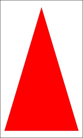
You can also call the Actor::SetColor(Color::RED) function to get a more colorful end result, as shown in the following figure.
Figure: Triangle
Drawing a Cube
To draw a colored cube, you need a slightly more complicated shader and geometry format:
- Create the shader source code:
- The
aPositionattribute must be changed tovec3, since the cube has 3 dimensions:const char* VERTEX_SHADER = DALI_COMPOSE_SHADER( attribute mediump vec3 aPosition; attribute mediump vec3 aColor; uniform mediump mat4 uMvpMatrix; uniform mediump vec3 uSize; varying mediump vec4 vColor; void main() { mediump vec4 vertexPosition = vec4( aPosition, 1.0 ); vertexPosition.xyz *= uSize; gl_Position = uMvpMatrix * vertexPosition; vColor = vec4( aColor, 1.0 ); } ); - Each face of the cube is given a different color using the
vColorvarying:const char* FRAGMENT_SHADER = DALI_COMPOSE_SHADER( varying mediump vec4 vColor; void main() { gl_FragColor = vColor; } );
- The
- Create the cube geometry.
The vertex format is extended to match the shader. Each of the 6 cube faces requires 4 vertices (24 in total). Each vertex consists of a
vec3and RGB color component.Property::Map vertexFormat; vertexFormat["aPosition"] = Property::VECTOR3; vertexFormat["aColor"] = Property::VECTOR3; PropertyBuffer vertices = PropertyBuffer::New( vertexFormat ); struct Vertex { Vector3 position; Vector3 color; }; Vertex vertexData[24] = { { Vector3( -0.5, -0.5, 0.5 ), Vector3( 1.0, 0.0, 0.0 ) }, { Vector3( 0.5, -0.5, 0.5 ), Vector3( 1.0, 0.0, 0.0 ) }, { Vector3( -0.5, 0.5, 0.5 ), Vector3( 1.0, 0.0, 0.0 ) }, { Vector3( 0.5, 0.5, 0.5 ), Vector3( 1.0, 0.0, 0.0 ) }, { Vector3( -0.5, -0.5, -0.5 ), Vector3( 0.0, 1.0, 0.0 ) }, { Vector3( 0.5, -0.5, -0.5 ), Vector3( 0.0, 1.0, 0.0 ) }, { Vector3( -0.5, 0.5, -0.5 ), Vector3( 0.0, 1.0, 0.0 ) }, { Vector3( 0.5, 0.5, -0.5 ), Vector3( 0.0, 1.0, 0.0 ) }, { Vector3( -0.5, -0.5, -0.5 ), Vector3( 0.0, 0.0, 1.0 ) }, { Vector3( 0.5, -0.5, -0.5 ), Vector3( 0.0, 0.0, 1.0 ) }, { Vector3( -0.5, -0.5, 0.5 ), Vector3( 0.0, 0.0, 1.0 ) }, { Vector3( 0.5, -0.5, 0.5 ), Vector3( 0.0, 0.0, 1.0 ) }, { Vector3( -0.5, 0.5, -0.5 ), Vector3( 1.0, 1.0, 0.0 ) }, { Vector3( 0.5, 0.5, -0.5 ), Vector3( 1.0, 1.0, 0.0 ) }, { Vector3( -0.5, 0.5, 0.5 ), Vector3( 1.0, 1.0, 0.0 ) }, { Vector3( 0.5, 0.5, 0.5 ), Vector3( 1.0, 1.0, 0.0 ) }, { Vector3( -0.5, -0.5, -0.5 ), Vector3( 1.0, 0.0, 1.0 ) }, { Vector3( -0.5, 0.5, -0.5 ), Vector3( 1.0, 0.0, 1.0 ) }, { Vector3( -0.5, -0.5, 0.5 ), Vector3( 1.0, 0.0, 1.0 ) }, { Vector3( -0.5, 0.5, 0.5 ), Vector3( 1.0, 0.0, 1.0 ) }, { Vector3( 0.5, -0.5, -0.5 ), Vector3( 0.0, 1.0, 1.0 ) }, { Vector3( 0.5, 0.5, -0.5 ), Vector3( 0.0, 1.0, 1.0 ) }, { Vector3( 0.5, -0.5, 0.5 ), Vector3( 0.0, 1.0, 1.0 ) }, { Vector3( 0.5, 0.5, 0.5 ), Vector3( 0.0, 1.0, 1.0 ) }, }; const unsigned short INDEX_CUBE[] = { 0, 2, 3, 0, 3, 1, 5, 7, 6, 5, 6, 4, 8, 10, 11, 8, 11, 9, 14, 12, 13, 14, 13, 15, 16, 17, 19, 16, 19, 18, 22, 23, 21, 22, 21, 20 }; vertices.SetData( vertexData, 24 ); Geometry geometry = Geometry::New(); geometry.AddVertexBuffer( vertices ); geometry.SetIndexBuffer( &INDEX_CUBE[0], sizeof(INDEX_CUBE)/sizeof(INDEX_CUBE[0]) ); geometry.SetType( Geometry::TRIANGLES ); - Create a renderer.
There is no
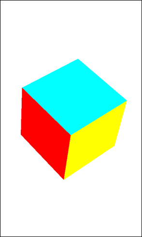
SetColor()function needed for the actor, since you are not using theuColoruniform. Face culling is enabled to hide the backward facing sides of the cube.Shader shader = Shader::New( VERTEX_SHADER, FRAGMENT_SHADER ); Renderer renderer = Renderer::New( geometry, shader ); renderer.SetProperty( Renderer::Property::FACE_CULLING_MODE, FaceCullingMode::BACK ); Actor actor = Actor::New(); float length = stage.GetSize().width * 0.5f; actor.SetSize( length, length, length ); actor.SetParentOrigin( ParentOrigin::CENTER ); actor.AddRenderer( renderer ); stage.Add( actor ); mAnimation = Animation::New( 10.0f ); mAnimation.AnimateTo( Property( actor, Actor::Property::ORIENTATION ), Quaternion( Radian( Degree( 180 ) ), Vector3::ZAXIS ) ); mAnimation.AnimateTo( Property( actor, Actor::Property::ORIENTATION ), Quaternion( Radian( Degree( 180 ) ), Vector3::YAXIS ) ); mAnimation.Play();
The following figure shows the running animation.
Was this document helpful?
We value your feedback. Please let us know what you think.