

Edje
This programming guide shows you how to write an EDC file that can be used to theme a Tizen application. It describes concepts about parts positioning and resizing. It also explains part animations that can be done through programs.
Basic Concepts
What is an EDC File?
An EDC file stands for Edje data collection. It is a text file that contains special code format describing the position, size, and other parameters of graphical elements that compose the visual aspect of your application. In addition to graphical elements, it can also handle sounds.
The syntax for the Edje data collection files follows a simple structure of "blocks { .. }" that can contain "properties: ..", more blocks, or both.
An EDC file has the ".edc" extension.
Compiling EDC File
EDC file needs to be compiled into a ".edj" file using Edje library tools. After compiling the ".edj" file can be used by a native Tizen application.
Here is an example about compiling helloworld.edc to ".edj" file using edje_cc tool:
$ edje_cc helloworld.edc
This command creates a helloworld.edj file.
An EDC file can use external files such as sounds, images, or fonts. The path to these resources are passed to the edje_cc tool so that they are included in the final ".edj" file.
$ edje_cc -sd $SOUNDS_DIR -fd $FONTS_DIR -id $IMAGES_DIR
SOUNDS_DIR, FONTS_DIR, and IMAGES_DIR are the paths for sounds, fonts, and images resources respectively.
Tizen SDK calls edje_cc during the project building if it finds an EDC source file in the ./res/edje/ directory.
Building file: ../res/edje/helloworld.edc
Invoking: EDC Resource Compiler
edje_cc -sd ../edje/sounds -fd ../edje/fonts -id ../edje/images ../res/edje/helloworld.edc ../res/edje/helloworld.edj
The Tizen SDK compilation log extract shows you that if your EDC file uses pictures, they must be copied to the ./edje/images directory. Fonts and sounds go to the ./edje/fonts and ./edje/sounds directory respectively. The SDK builds the helloworld.edj file in the ./res/edje/ folder.
Writing Simple EDC File
The code example below shows you the structure of an EDC file. It is a collection of groups that contain parts and programs.
collections
{
   group
   {
      name: "my_group";
      parts {}
      programs {}
   }
}
Groups are identified with a name, parts correspond to the graphical elements. Each one of them can have several states that describe a specific position, size, and visual aspect. Programs contain the program code, such as interaction with the main application through signals. Also animations are defined here (changing a part state using an animated transition).
The description field is where the state of a part is written.
part
{
   description
   {
      state: "default" 0.0;
   }
   description
   {
      state: "state1" 0.0;
   }
   description
   {
      state: "state2" 0.0;
   }
}
As an example, here is a simple EDC file that contains only one part and one program. The part is a rectangle with blue state and red state, the program changes the state from blue to red when user clicks on the rectangle.
collections
{
   group
   {
      name: "example";
      parts
      {
         // create the part
         part
         {
            name: "rectangle";
            // set the type to RECT (rectangle)
            type: RECT;
            // default state (blue color)
            description
            {
               state: "default" 0.0;
               align: 0.0 0.0;
               // blue color
               color: 0 0 255 255;
            }
            // second state (red color)
            description
            {
               state: "red" 0.0;
               align: 0.0 0.0;
               // red color
               color: 255 0 0 255;
            }
         }
      }
      programs
      {
         // create a program
         program
         {
            name: "change_color";
            // program is triggered on mouse click
            signal: "mouse,clicked,*";
            source: "*";
            // set the red state of the "rectangle" part
            action: STATE_SET "red" 0.0;
            target: "rectangle";
         }
      }
   }
}
A program is triggered when receiving a signal from a specific source (here all the sources are taken into account). When launched, it does the action (changing the state of a part) on the target (the rectangle).
Animating Theme Using Programs
The previous example showed how to change the state of a part. It is also possible to use the transition parameter to create an animation between the 2 states. You can specify a transition type (ACCELERATE, DECELERATE, SINUSOIDAL, LINEAR, ...) and length (in seconds) of the transition.
The following code example animates the previous state change using a linear transition of 2 seconds.
programs
{
   program
   {
      name: "change_color";
      signal: "mouse,clicked,*";
      source: "*";
      action: STATE_SET "red" 0.0;
      target: "rectangle";
      transition: LINEAR 2.0;
   }
}
Edje calculates all frames needed for the animation. The result is a smooth animation between the two states and it takes 2 seconds.
Positioning Basic Parts
Size of a part (in pixels) is set using the min and max parameters. The following code example sets the minimum and maximum size of the rectangle part to 200x200 px.
part
{
   name: "rectangle";
   type: RECT;
   description
   {
      state: "blue" 0.0;
      align: 0.0 0.0;
      // set the size to 200x200
      min: 200 200;
      max: 200 200;
      // blue color
      color: 0 0 255 255;
   }
}
Position of the parts is defined in the rel1 and rel2 blocks. rel1 and rel2 blocks are used to define respectively the upper-left corner and the lower-right corner of the part. Position can be defined relatively to other parts (with the relative parameter) as an offset (offset parameter). When using relative positioning, the to, to_x and to_y parameters are used to define to which part the relative positioning is done. If nothing else is specified, the positioning is relative to the parent's part.
To demonstrate the relative positioning, here is a code example that creates another part and positions it under the first part (the upper-left corner of the new part will start at the lower-left corner of the previous one).
part
{
   name: "rectangle2";
   type: RECT;
   description
   {
      state: "green" 0.0;
      align: 0.0 0.0;
      // set the size to 200x200
      min: 200 200;
      max: 200 200;
      // green color
      color: 0 255 0 255;
      // set the position
      // rel1 is relative to "rectangle"
      rel1
      {
         relative: 0.0 1.0;
         to: "rectangle";
      }
      // rel2 is relative to the parent
      rel2
      {
         relative: 1.0 1.0;
      }
   }
}
| Note |
|---|
| The align parameter defines how the parts align themselves in the main window if their size is smaller than the main window. If nothing is specified, the parts are aligned in the center of the window. |
Adding Offset to Relative Positioning
The rel1 and rel2 structures also support offset which is a complement to the relative positioning: the corners are first placed according to their relative parameters and then adjusted using the offsets.
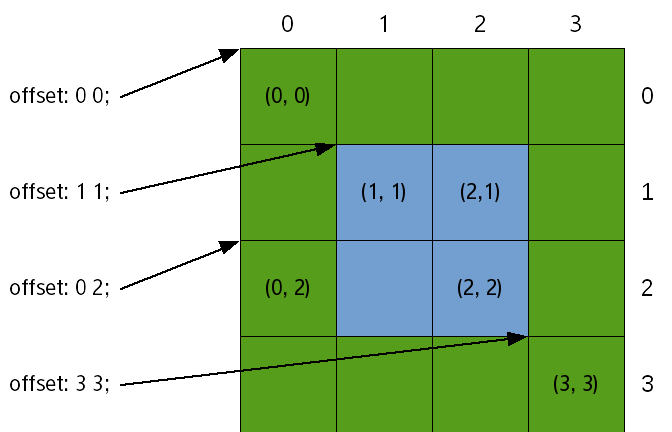
The picture below shows the pixel positions for a 4x4 rectangle. The indices start in the top-left corner at (0, 0) increase to the right and to the bottom. Since the indices have started at 0, the 4th pixel has an index of 3.
Therefore, in order to create a 2x2 blue rectangle centered inside that green square, the top-left corner has to be (1, 1) and the bottom-right one has to be (2, 2).
Figure: Offset indices
Edje needs the following things defined:
- the part coordinates depending on the size and position of the green rectangle
- the relative component of positions is the same: the top-left corner of the green rectangle
- the top-left pixel is (1, 1) and the bottom-right one is (2, 2)
The following code example defines these things:
name: "blue rectangle";

rel1.to: "green rectangle";
rel1.relative: 0 0;
rel1.offset: 1 1;

rel2.to: "green rectangle";
rel2.relative: 0 0;
rel2.offset: 2 2;
For most tasks, relative positioning is simpler than using offsets. Offsets are usually left for fine-tuning and creating borders.
The example below is similar to the previous one but uses relative positioning instead of offsets to achieve an equivalent at 4x4 but could scale to larger sizes.
The blue square starts at 25% of the green square (both vertically and horizontally) and ends at 75% of it (again, both vertically and horizontally).
Just like in the previous example, the blue rectangle is named and Edje is told what the object of reference is:
name: "blue rectangle";
rel1.to: "green rectangle";
rel2.to: "green rectangle";
The image below shows how to refer pixels using relative positioning when the offsets are (0, 0).
Figure: Relative positioning
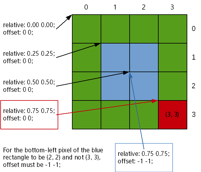
Note the addressing of pixels: (0, 0) is addressed through relative: 0 0; offset 0 0; and each additional 0.25 in the relative field gives a 1-pixel move. With this, the pixel addressed through relative: 0.75 0.75; offset: 0 0; is at (3, 3) and not (2, 2)!.
This comes from a design choice in Evas and Edje which favor simplicity. In the examples shown in this guide, there are 4 pixels and therefore when the [0; 1) range is divided in 4, the result is [0; 0.25), [0.25; 0.50), [0.50; 0.75), [0.75; 0.100). With Edje, the value used to refer to each segment is the left bound and therefore, 0.75 refers to [0.75; 0.100), i.e. the bottom-right pixel of the green rectangle and not the 3/4th one.
The way to refer to the pixel right before is to set the rel2 bound to relative: 0.75 0.75;, as would be expressed naturally, and offset: -1 -1;. This can also be understood as extending the rectangle up to 75% of its parent with the upper bound excluded (as shown in the [0.50; 0.75)).
Since -1 -1 is the most common offset wanted for rel2, it is the default value; i.e. the default behavior is practical.
Calculating Edje Object Total Size
When the EDC file is composed of a lot of parts, Edje calculates the size of the global Edje object, by taking all the parts and their parameters into account. Some parameters have an role in this calculation and affect the global size:
- min and max: these define the minimum and the maximum size of a part.
- rel1 and rel2: these specify the relative position of a part.
- align: this relates to the alignment of the part in the parent's object.
- fixed: this defines if the part has a fixed size.
| Note |
|---|
| fixed parameter can only be used on TEXTBLOCK type parts. Setting this parameter to fixed: 1 1 will not take into account the part for the calculation of the global size. |
Using Edje Size Hints
Any Evas_Object can have hints, so that the object knows how to properly position and resize. Edje uses these hints when swallowing an Evas_Object to position and resize it in the SWALLOW part of the EDC file.
Size hints are not a size enforcement, they just tell the parent object the desired size for this object. Then, the parent tries to get as close as possible to the hint.
Hints are set in an Evas_Object using the evas_object_size_hint_*() functions.
Min Size Hint
This sets the hints for the object's minimum size, given in pixels.
Here the horizontal and vertical min size hints of an Evas_Object are set to 0 pixels.
Evas_Object *object;
evas_object_size_hint_min_set(object, 0, 0);
Max Size Hint
This sets the hints for the object's maximum size, given in pixels.
Here the horizontal and vertical max size hints of an Evas_Object are set to 200 pixels.
evas_object_size_hint_max_set(object, 200, 200);
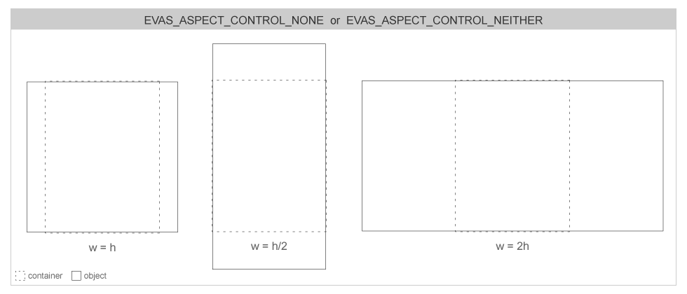
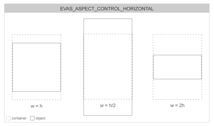
Aspect Size Hint
This sets the hints for the object's aspect ratio. Available aspect size hints are:
- EVAS_ASPECT_CONTROL_NONE
- EVAS_ASPECT_CONTROL_HORIZONTAL
- EVAS_ASPECT_CONTROL_VERTICAL
- EVAS_ASPECT_CONTROL_BOTH
The other parameters are aspect width and height ratio. These integers are used to calculate the proportions of the object. If aspect ratio terms are null, the object's container ignores the aspect and scale of the object and occupies the whole available area.
Figure: Aspect control
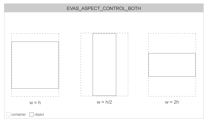
The following code example sets the aspect size hint to EVAS_ASPECT_CONTROL_BOTH with a width of 100 and a height of 200. So aspect ratio should be 1/2.
evas_object_size_hint_aspect_set(object, EVAS_ASPECT_CONTROL_BOTH, 100, 200);
Align Size Hint
This sets the hints for the object's alignment. This hint is used when the object size is smaller than its parent's. The special EVAS_HINT_FILL parameter uses maximum size hints with higher priority, if they are set. Also, any padding hints set on objects are added up to the alignment space on the final scene composition.
Figure: Alignment
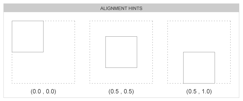
In the code below, the special EVAS_HINT_FILL parameter is used.
evas_object_size_hint_align_set(object, EVAS_HINT_FILL, EVAS_HINT_FILL);
Weight Size Hint
This sets the hints for the object's weight. The weight tells to a container object how the given child is resized. Using EVAS_HINT_EXPAND parameter asks to expand the child object's dimensions to fit the container's own.
When several child objects have different weights in a container object, the container distributes the space it has to layout them by those factors. Most weighted children get larger in this process than the least ones.
Here the container is asked to expand the object in both directions.
evas_object_size_hint_weight_set(object, EVAS_HINT_EXPAND, EVAS_HINT_EXPAND);
Padding Size Hint
This sets the hints for the object's padding space. Padding is extra space an object takes on each of its delimiting rectangle sides. The padding space is rendered transparent. Four hints can be defined, for the left, right, top, and bottom padding.
Figure: Padding
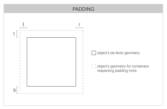
Here the padding hints are set to 5 pixels on each side of the object.
evas_object_size_hint_padding_set(object, 5, 5, 5, 5);
Scaling Objects
Part Scaling
When scaling an Edje object, only the parts that are declared scalable in the EDC file follow the scale request. This is done using the "scale" parameter.
As an example, the previous "rectangle2" part is set as scalable, so that it is scaled when the Edje object is scaled.
part
{
   name: "rectangle2";
   type: RECT;
   scale: 1;
   description
   {
      state: "green" 0.0;
   }
}
Using Image Set
When using images in the Edje EDC file, image file names must be listed in a images block, so that Edje can use them in the theme. In this block, the compression level and compression method of the image can also be defined.
Here is an example of an images block that lists two image files.
images
{
   image: "image1.jpg" COMP;
   image: "image2.png" LOSSY 99;
}
As the devicescan have different screen sizes and resolutions, it is possible to define that the used image set depends on the resolution.
In the example below the image named "image3" selects different files depending on image size.
images
{
   set
   {
      name: "image3";
      image
      {
         image: "image3_1.png" LOSSY 90;
         size: 0 0 50 50;
      }
      image
      {
         image: "image3_2.png" LOSSY 90;
         size: 51 51 200 200;
      }
      image
      {
         image: "image3_3.png" LOSSY 90;
         size: 201 201 500 500;
      }
   }
}
This is done with the "size" attribute that specifies the minimal width and height and maximal width and height. If the width and height of the object are below 50px, image3_1.png picture file is used. If they are bigger than 201px, image3_3.png file is used.
Resizing Borders
Sometimes it is needed to keep the borders of an image intact when resizing or scaling it. The border attribute is here to do that.
border [left] [right] [top] [bottom]
If set, the area (in pixels) of each side of the image is displayed as a fixed size border, from the side -> inwards. This prevents the corners from being changed on a resize.
Here is a code example how to set a border of 10px on each side of the image. This 10px border will not be resized when scaling the image.
part
{
   name: "image_border";
   type: IMAGE;
   scale: 1;
   description
   {
      image
      {
         normal: "image1.jpg";
         border: 10 10 10 10;
      }
   }
}
Edje Swallow
The parent of all layout components is Edje. Edje as explained in the Edje Blocks is a library which convert edc files into Evas object. EDC is a description language. It means that the objects of interface are described by using text description. One of its main features is the possibility to create "Swallows" objects. When this kind of object is added in an Evas, it contains any other Evas_Object. To create a swallow part, create first the EDC file:
collections
{
   group
   {
      name: "container";
      parts
      {
         part
         {
            name: "part.swallow"
            type: SWALLOW;
            description
            {
               state: "default" 0.0;
               rel1.offset: 31 31;
               rel2.offset: -32 -32;
            }
         }
      }
   }
}
This EDC describes a group named "container", with one part inside of type SWALLOW and with the name part.swallow. This part is centered inside the parent (it is the default behavior) but there are 32 pixels free all around this part. Use edje_cc to compile the EDC file into a binary EDJ file:
edje_cc -o container.edj container.edc
Create an Edje object and load this file:
edje = edje_object_add(evas_object_evas_get(parent));
edje_object_file_set(edje, "container.edj", "container");
| Note |
|---|
| edje_object_add as opposed as all elementary object, does not take an Evas_Object as a parent. Give it the Evas on which the object is added. As the parent is already added on an Evas by elementary, retrieve a reference on it by using the evas_object_evas_get() function. |
edje_object_file_set is used to set the Edje file from which the object is loaded. The object itself is the name of the group as defined in the EDC file, in this case it is "container".
Use the API edje_object_swallow to swallow any kind of Evas_Object inside.
ic = elm_icon_add(parent);
elm_image_file_set(ic, "c1.png", NULL);
edje_object_part_swallow(edje, "part.swallow", ic);
| Note |
|---|
| The elm_image_file_set() function parameters are linked to Edje. The second argument in this example is a PNG file; however, it can also be an Edje file. In that case, the third argument must be the Edje group to load, exactly as previously shown with the edje_object_file_set() function. |
Create complex layout for your application with Edje. It is may not be the most easy way, but it is the most powerful. This Edje layout is used all around elementary and is the basis of the layout component.
ELM Layout
Layout is a container component. For the basic use of the elm_layout with a default style, see the Layout Guide (in mobile and wearable applications). Elm layout takes a standard Edje design file and wraps it in a UI component. Layouts are the basis of graphical UI components which are used in Elementary.
Adding Layout
Create a new elementary layout using elm_layout_add:
Evas_Object *layout;
layout = elm_layout_add(parent);
As for Edje swallows, load an Edje file. Create first an Edje file, that contains a black rectangle and an icon in the center.
images
{
   image: "c1.png" COMP;
}

collections
{
   group
   {
      name: "my_layout";
      parts
      {
         part
         {
            name: "background";
            type: RECT; description
            {
               state: "default" 0.0; color: 0 0 0 255;
            }
         }
         part
         {
            name: "background";
            type: IMAGE;
            description
            {
               state: "default" 0.0;
               rel1.offset: 31 31;
               rel2.offset: -32 -32;
               default.image: "c1.png";
            }
         }
      }
   }
}
Compile it with edje_cc -o edje_example.edj edje_example.edc.
This file can be loaded with elm_layout_file_set:
elm_layout_file_set(layout, "edje_example.edj", "my_layout");
The layout component may contain as many parts/children as described in its theme file (EDC). Some of these children can have special types:
- SWALLOW (content holder)
- BOX
- TABLE
Only one object can be added to a SWALLOW. The elm_layout_content_set()/get/unset functions are used to manage objects in a SWALLOW part. After being set to this part, the object's size, position, visibility, clipping and other description properties are controlled by the description of the given part (inside the Edje theme file).
The BOX layout can be used through the elm_layout_box_*() set of functions. It is very similar to the elm_box component but the BOX layout's behavior is completely controlled by the Edje theme. The TABLE layout is like the BOX layout, the difference is that it is used through the elm_layout_table_*() set of functions.
Signals
Elm can send Edje signals to the EDC part by using the elm_layout_signal_emit. You can also use elm_layout_signal_callback_add to receive signals.
Use the following code to listen to any signals sent by the layout:
elm_layout_signal_callback_add(layout, "*", "*", _signal_cb, NULL);

static void _signal_cb(void *data, Evas_Object *obj, const char *emission, const char *source)
{
   printf("Info received from layout : %s %s\n", emission, source);
}
For more details on this, see the section on edje signals and layouts.
EDC Reference
The documentation includes an extensive language reference. You can also access the page on the part block directly.
Quick How-tos
Adding Element on Screen
Add a new part inside the parts block.
Using Image
List the image in the images block, make sure the part has type "IMAGE" and set the normal property inside description.image of part.
Using Same Color Definitions Across Multiple Elements
Define a color class and set the description.color_class property.
Positioning or Resizing a Part (Relative and Absolute Positioning)
Fill in the rel1 and rel2 structures inside the description block.
Hiding Part
Set the visible property to 0.
Animating Part
Create several description blocks inside your part and give each of them a different value for state. Set one description for the initial state and one for the end state.
Create a program with an action that is STATE_SET "end_state" 0.0; and with a target that is the name of the part. You can also set a non-default transition.
When defining the second description, inherit from the first part in order to re-use the values which are already defined.
The after property of the program block is used to trigger another program after the animation is done. It can be used to trigger another animation or to emit a signal to the C part of the program.
Making Genlist Item Theme
Create a group with one part element for each part that can be filed from the C code and set the items properties inside the group element:
items: "texts" "text_part_1 text_part_2";
items: "icons" "image_part_1 image_part_2";
On the C side, the text_get and content_get callback are called respectively with text_part_1 and text_part_2, and image_part_1 and image_part_2.
