
[UI Sample] RelativePositioning Sample Overview
The [UI Sample] RelativePositioning sample application demonstrates how to position an object in relation to another object using the EDC to keyword.
The sample uses UI components, such as elm_conformant, for view management, containers, such as elm_layout, for UI component management inside the view, and objects, such as elm_rectangle, for the contents of the EDC view.
The following figure illustrates the main screen of the sample, its wireframe structure, and the UI component tree.
Figure: [UI Sample] RelativePositioning main screen
![[UI Sample] RelativePositioning main screen](../images/relative_main.png)
![[UI Sample] RelativePositioning UI component tree](../images/edc_main_tree.png)
Application Layout
The create_base_gui() function creates the window, conformant, and layout. The EDC file is then inserted into the layout.
static void
create_base_gui(appdata_s *ad)
{
   char edj_path[PATH_MAX] = {0, };

   // Create window
   ad->win = elm_win_util_standard_add(PACKAGE, PACKAGE);
   elm_win_conformant_set(ad->win, EINA_TRUE);
   elm_win_autodel_set(ad->win, EINA_TRUE);

   if (elm_win_wm_rotation_supported_get(ad->win))
   {
      int rots[4] = {0, 90, 180, 270};
      elm_win_wm_rotation_available_rotations_set(ad->win, (const int *)(&rots), 4);
   }

   evas_object_smart_callback_add(ad->win, "delete,request", win_delete_request_cb, NULL);

   // Create conformant
   ad->conform = elm_conformant_add(ad->win);
   elm_win_indicator_mode_set(ad->win, ELM_WIN_INDICATOR_SHOW);
   elm_win_indicator_opacity_set(ad->win, ELM_WIN_INDICATOR_OPAQUE);
   evas_object_size_hint_weight_set(ad->conform, EVAS_HINT_EXPAND, EVAS_HINT_EXPAND);
   elm_win_resize_object_add(ad->win, ad->conform);
   evas_object_show(ad->conform);

   // Create base layout
   app_get_resource(EDJ_FILE, edj_path, (int)PATH_MAX);
   ad->layout = elm_layout_add(ad->win);
   elm_layout_file_set(ad->layout, edj_path, GRP_MAIN);
   evas_object_size_hint_weight_set(ad->layout, EVAS_HINT_EXPAND, EVAS_HINT_EXPAND);
   eext_object_event_callback_add(ad->layout, EEXT_CALLBACK_BACK, layout_back_cb, ad);
   elm_object_content_set(ad->conform, ad->layout);

   // Show the window after the base GUI is set up
   evas_object_show(ad->win);
}
EDC View
The following figure illustrates the EDC view wireframe and tree structure.
Figure: EDC view
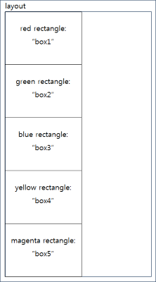
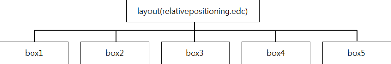
The relativepositioning.edc file is used to position the objects in the EDC view. The file uses the EDC to keyword for specifying relative positioning. In this sample, the EDC file consists of 5 rectangles positioned in relation to one another.
The following code is the entire EDC script of the relativepositioning.edc file:
collections
{
   group
   {
      name: "main";
      parts
      {
         part
         {
            name: "box1";
            type: RECT;
            mouse_events: 0;
            description
            {
               state: "default" 0.0;
               align: 0.0 0.0;
               rel1 { relative: 0.0 0.0; }
               rel2 { relative: 0.5 0.2; }
               color: 255 0 0 128;
            }
         }
         part
         {
            name: "box2";
            type: RECT;
            mouse_events: 0;
            description
            {
               state: "default" 0.0;
               rel1
               {
                  relative: 0.0 1.0;
                  to: "box1";
               }
               rel2
               {
                  relative: 1.0 2.0;
                  to: "box1";
               }
            color: 0 255 0 128;
            }
         }
         part
         {
            name: "box3";
            type: RECT;
            description
            {
               state: "default" 0.0;
               rel1
               {
                  relative: 0.0 1.0;
                  to: "box2";
               }
               rel2
               {
                  relative: 1.0 2.0;
                  to: "box2";
               }
            color: 0 0 255 128;
            }
         }
         part
         {
            name: "box4";
            type: RECT;
            mouse_events: 0;
            description
            {
               state: "default" 0.0;
               rel1
               {
                  relative: 0.0 1.0;
                  to: "box3";
               }
               rel2
               {
                  relative: 1.0 2.0;
                  to: "box3";
               }
               color: 255 255 0 128;
            }
         }
         part
         {
            name: "box5";
            type: RECT;
            mouse_events: 0;
            description
            {
               state: "default" 0.0;
               rel1
               {
                  relative: 0.0 1.0;
                  to: "box4";
               }
               rel2
               {
                  relative: 1.0 2.0;
                  to: "box4";
               }
               color: 255 0 255 128;
            }
         }
      }
   }
}
To position a part relative to another object, use the to keyword to specify the object. The position of the part becomes dependent on the position of the object. The relative position is calculated from the left-top corner of the target object.
The region occupied by box1 (a red rectangle) is determined by ratio: its left-top corner is at (0.0, 0.0) and right-bottom corner at (0.5, 0.2). The region occupied by box2 (a green rectangle) is determined by ratio relative to box1: its left-top corner is positioned at (0.0, 1.0), which is the left-bottom corner of box1, and its right-bottom corner is positioned at (1.0, 2.0), which is once the width and twice the height of box1. This same rule is applied to each subsequent part, creating a vertical column of same-sized rectangles.
